


News
Introduction to Voltage Sensor Solutions for Pole-Mounted Switches
Date:2025-06-20
Content:
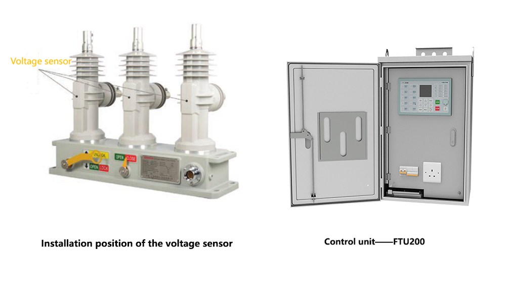
Voltage, current, and frequency are fundamental and critical parameters in distribution systems. It is essential to accurately acquire these parameters and transmit them to the FTU (the control unit of the pole-mounted switch). Voltage acquisition primarily relies on voltage sensors. This article introduces several common voltage sensor solutions.
1. Resistive Voltage Divider Sensor (RVDS)
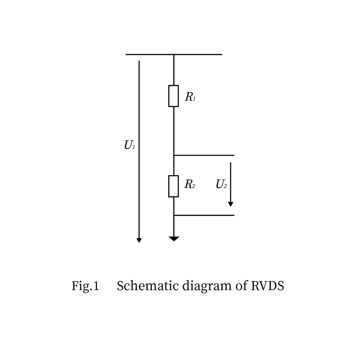
Principle: This is the most direct voltage division principle, as shown in Figure 1. It utilizes two or more series-connected high-precision, high-stability resistors (R1 is the high-voltage arm resistor, R2 is the low-voltage arm resistor) connected between the high-voltage phase line (or phase line to ground). The measured high voltage U_in drops mostly across the high-voltage arm resistor R1, and a low-voltage signal U_out proportional to the input voltage is extracted from across the low-voltage arm resistor R2.
Relationship :U_out = U_in * (R2 / (R1 + R2))
Advantages:
Simple principle, straightforward structure.
Relatively low cost.
Good linearity (resistors themselves have good linearity).
Fast response speed (only affected by distributed capacitance).
Disadvantages:
Heating Issue: R1 has a very high resistance (typically MΩ level), but the current flowing through it generates heat, causing temperature rise. This affects resistance stability (requires resistors with extremely low temperature coefficients) and long-term reliability.
Power Loss: Continuous active power loss exists.
High Insulation Requirements: The high-voltage arm resistor and its connections require high-voltage insulation, potentially leading to larger size.
Frequency Characteristics : Affected by the resistor's own distributed capacitance and stray capacitance, high-frequency response may be limited.
Noise Immunity: The low-voltage output signal has a small amplitude and is susceptible to electromagnetic interference (EMI).
2. Capacitive Voltage Divider Sensor (CVDS)
Principle: As shown in Figure 3, it utilizes two or more series-connected high-voltage capacitors (C1 is the high-voltage arm capacitor, C2 is the low-voltage arm capacitor) connected between the high-voltage phase line (or phase line to ground). The measured high voltage U_in is divided inversely proportional to the capacitive reactance (Xc = 1/(2πfC)).
Ideal Relationship (ignoring losses): U_out = U_in * (C1 / (C1 + C2))
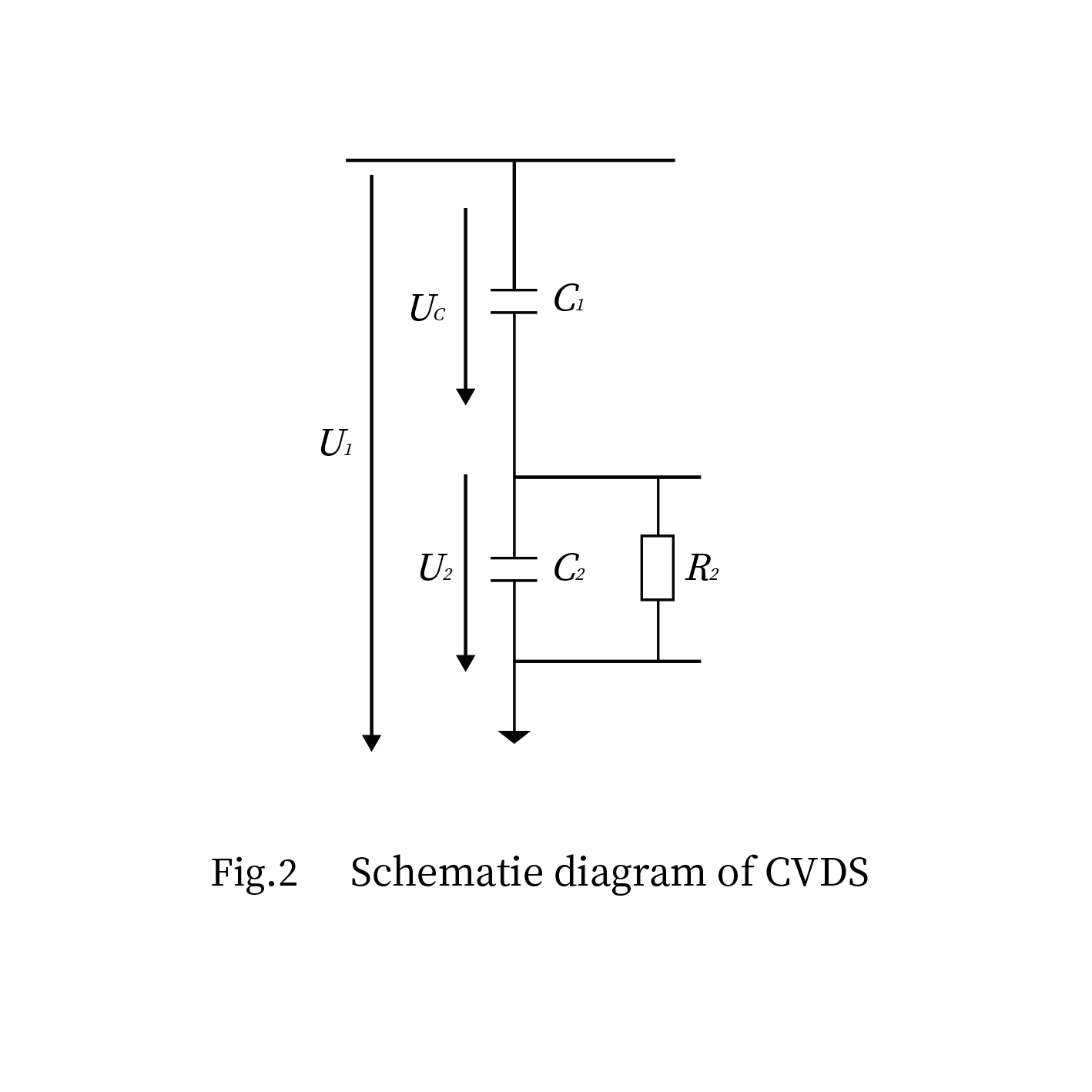
(Note: Actual division is based on capacitive reactance and is frequency-dependent).
Typically,this results in C1 << C2, , so U_out is very small and requires subsequent signal conditioning (high input impedance amplifier).
Advantages :
Negligible Power Consumption: With ideal capacitors, there is almost no active power loss (only dielectric losses), resulting in minimal temperature rise.
Good Frequency Characteristics: Stable performance over a wide frequency range (power frequency and its harmonics).
Good Insulation: High-voltage capacitors inherently have good insulation properties.
Disadvantages :
Temperature/Humidity Effects :Capacitance value is susceptible to ambient temperature and humidity (changes in dielectric constant), requiring temperature compensation or the use of highly stable materials.
Large Low-Voltage Arm Capacitance:To obtain a sufficiently large U_out signal, C2 needs to be large (nF level), potentially affecting size and cost.
Requires High-Impedance Amplifier: The output impedance is high, necessitating connection to an amplifier with extremely high input impedance. Otherwise, loading effects will severely impact accuracy.
Noise Immunity: The output signal is small and has high impedance, making it susceptible to EMI.
Initial Accuracy and Stability: Manufacturing high-precision, high-stability high-voltage capacitors is difficult.
3. Resistance-Capacitance (RC) Voltage Divider Sensor(RCVDS)
Resistance-Capacitance Voltage Divider Sensors (RCVDS) can be categorized into parallel and series connection types based on their wiring configuration.The principle of the parallel RCVDS is shown in Figure 3; The principle of the series RCVDS is shown in Figure 4.
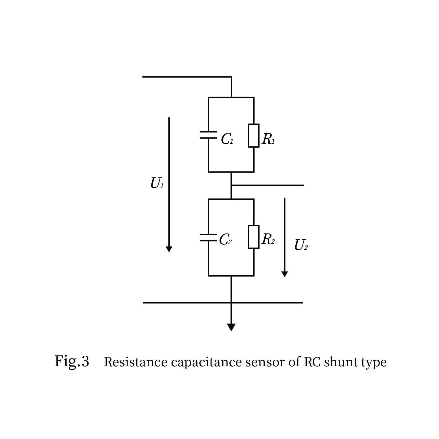
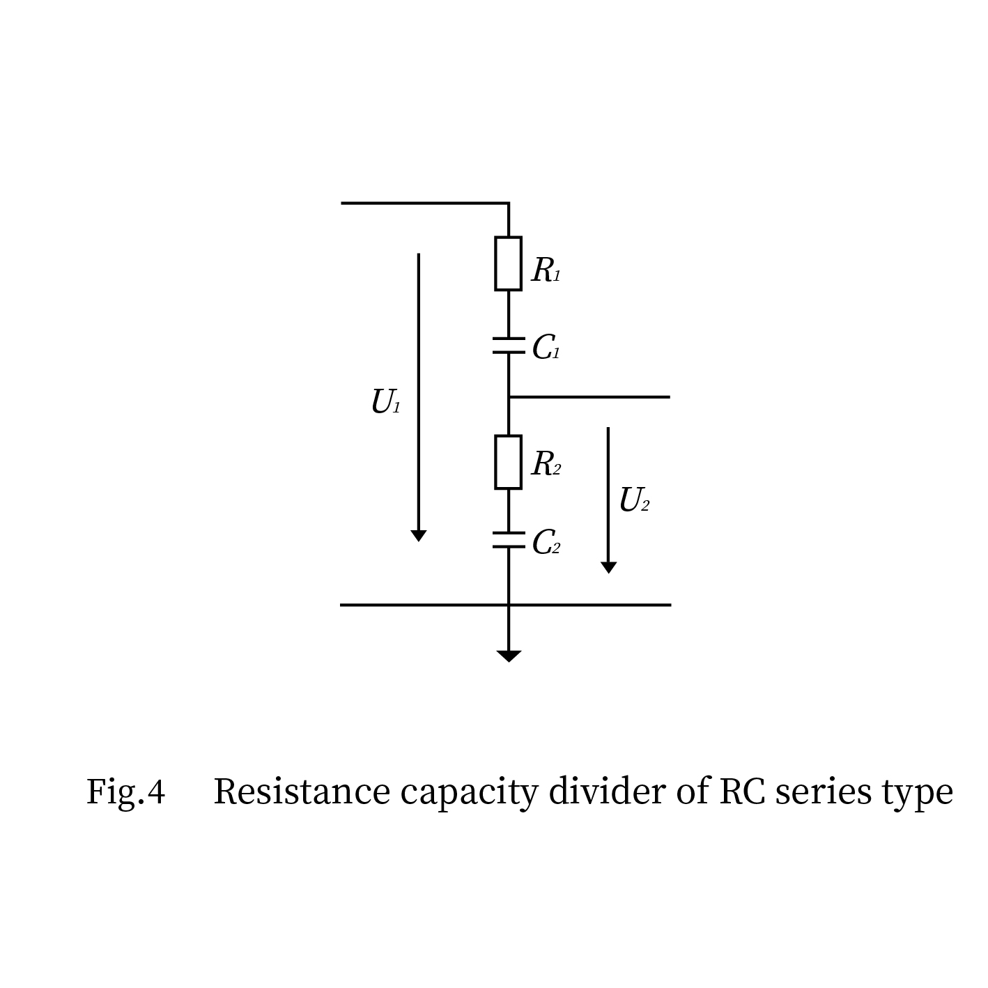
Principle: Combines the advantages of resistive and capacitive voltage division, achieving voltage division through a combination of resistors and capacitors.
Advantages: Integrates the benefits of both resistive and capacitive dividers, offering higher accuracy and being less affected by environmental influences.
Disadvantages: Design and manufacturing processes are relatively complex.
Conclusion:
As seen from the above voltage sensor solutions, each has its own advantages and disadvantages. Therefore, users need to comprehensively consider multiple factors based on their requirements and application scenarios, such as the sensor's stability, reliability, noise immunity, ease of installation and maintenance, and cost.


top
- Products
- Distribution Automation
- Outdoor Apparatus
- Fault Circuit Indicator
- Industrial Wireless Communication
- Software
- Solutions
- Utility Solutions
- Infrastructure Solutions
- Services
- Documents & Software
- Support
- Business Case
- Video
- about us
- Company
- Contact us
- Subscribe
- Career

Mobile viewing


© Copyright 2025 by www.fourfaithpower.com. All Rights Reserved. 闽ICP备08106834号-8

